


How to Pick the Right Air Compressor for Your Dry Cleaning Business
September 6, 2023
What Type of Commercial Air Compressor Does an Auto Shop Need?
September 13, 2023Industrial Air Compressor Installation: Complete Design & Setup Guide
Kaishan USA | August 9, 2023 | Uncategorized
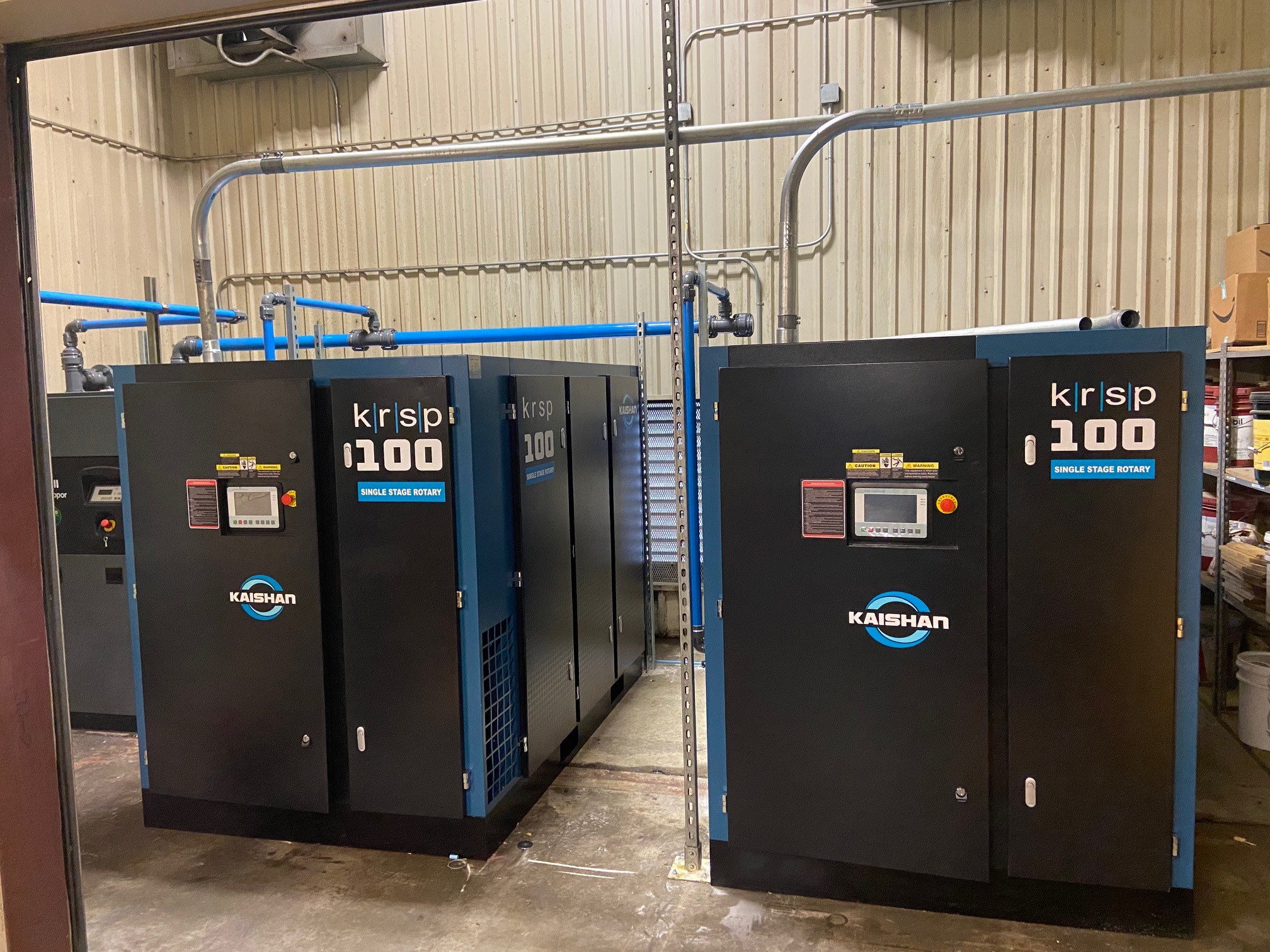
Ideally, your compressor will be installed on a flat and level concrete floor in a well-lit area that is clean, dust-free, dry and oil-free.
Installing an industrial air compressor requires careful planning, precise execution, and thorough understanding of compressed air systems. Whether you're setting up a new facility or upgrading existing equipment, proper installation is critical for optimal performance, energy efficiency, and equipment longevity. This comprehensive guide will walk you through every aspect of industrial air compressor installation, from initial design considerations to final testing and optimization.
Why Proper Air Compressor Installation Matters
Proper industrial air compressor installation is the foundation of a reliable compressed air system. When installation is done incorrectly, you face numerous consequences that can impact your operations and bottom line. Improper installation leads to reduced efficiency, with systems consuming up to 30% more energy than necessary. This inefficiency translates directly to higher operating costs and increased carbon footprint.
Beyond energy waste, poor installation causes excessive wear on components, significantly shortening equipment lifespan. You'll experience more frequent breakdowns, costly repairs, and unplanned downtime that disrupts production. Safety hazards also increase dramatically—improperly installed systems can develop leaks, overheat, or even fail catastrophically, putting personnel and equipment at risk.
Air quality suffers with poor installation as well. Contaminants like moisture, oil, and particles enter the compressed air stream, damaging downstream tools and processes. This leads to product quality issues in manufacturing environments and potential regulatory compliance problems.
Investing time and resources in proper industrial air compressor installation pays dividends through improved reliability, lower operating costs, enhanced safety, and consistent air quality. It's not just about following manufacturer recommendations—it's about creating a system that performs optimally for years to come.
Understanding the Design of Air Compressor Systems
The design of air compressor systems involves multiple interconnected components that must work together seamlessly. At its core, the design of air compressor systems focuses on delivering clean, dry compressed air at the required pressure and flow rate to meet your facility's needs.
Key components include the compressor itself (reciprocating, rotary screw, or centrifugal), air receiver tank for storage, air treatment equipment (dryers, filters), and distribution piping. Each element must be carefully selected and sized based on your specific requirements.
When considering compressors design, several factors come into play. The compressor type depends on your duty cycle, pressure requirements, and air quality needs. Rotary screw compressors, for example, are ideal for continuous operation in industrial settings, while reciprocating compressors suit intermittent use.
Air compressor design must account for the entire system, not just the compressor unit. This includes properly sized piping to minimize pressure drops, adequate storage to handle demand fluctuations, and appropriate treatment equipment to remove contaminants. The design should also consider future expansion, allowing for increased capacity without complete system overhaul.
A well-designed compressed air system balances performance, efficiency, and reliability. It incorporates proper controls to match output with demand, minimizes waste through leak prevention, and ensures air quality meets application requirements. Understanding these design principles is essential before proceeding with installation.
Pre-Installation Planning and Site Preparation
Assessing Your Air Requirements
Before beginning any industrial air compressor installation, you must accurately assess your air requirements. Start by calculating the CFM (Cubic Feet per Minute) and PSI (Pounds per Square Inch) needs for all tools and processes that will use compressed air. Create a comprehensive list of all air-consuming equipment, noting their individual CFM requirements at the operating pressure.
To calculate total CFM needs, add the requirements of all equipment that will operate simultaneously, then apply a usage factor (typically 25-50%) to account for intermittent use. For example, if you have ten tools each requiring 10 CFM, but only six will run at once, your base requirement is 60 CFM. Applying a 30% usage factor gives you 78 CFM as your minimum requirement.
Pressure requirements are equally important. Determine the highest pressure needed by any equipment, then add 5-10 PSI to account for system pressure drops. Most industrial applications require 90-100 PSI, but specialized processes may need higher pressures.
When planning the design of compressed air system, always consider future expansion. Adding 25-50% capacity to your calculations prevents the need for costly upgrades later. Also consider duty cycle—continuous operation requires more robust equipment than intermittent use.
Selecting the Right Location
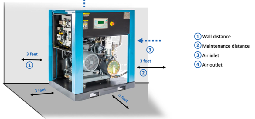
The location of your compressor significantly impacts performance and longevity. When selecting the right location, prioritize ventilation requirements above all else. Compressors generate substantial heat that must be dissipated to prevent overheating and reduced efficiency. The room should allow for adequate airflow around the unit, with minimum clearances specified by the manufacturer (typically 3 feet on all sides).
Noise considerations are equally important. Industrial compressors can produce significant noise levels, which can exceed OSHA limits and cause hearing damage. Place the compressor away from work areas, offices, and building perimeters near residential areas. If noise is a concern, consider soundproofing the room or selecting a low-noise compressor model like many Kaishan USA models.
The location should also be clean, dry, and well-lit. Avoid areas with excessive dust, chemical fumes, or moisture, as these contaminants can damage equipment and degrade air quality. The room should be easily accessible for maintenance and delivery of replacement parts.
For optimal air compressor room ventilation design, choose a location with access to fresh air intake and exhaust capabilities. This is crucial for maintaining proper operating temperatures and ensuring efficient compressor performance.
Indoor locations are preferable. But, in more moderate climates, like the southeastern and southwestern states of the U.S., it’s certainly possible to locate an air compressor outside, protecting it from the following conditions:
-
- The elements. You’ll want to ensure your compressor isn’t exposed to rain, snow and UV light.
- Temperature extremes. Avoid ambient temperatures above 122°F maximum or below 32°F minimum, taking into account any temperature rise from indirect or direct sunlight. Low ambient temperature package upgrades are available.
- Prevailing winds. Shield the machine from prevailing winds, which typically blow west to east in much of the U.S.
- Direct sunlight. Place your compressor out of direct sunlight, especially the morning or afternoon sun, to avoid damage to the compressor's HMI and additional machine heating.
- Poor ventilation. Make sure the roof isn’t so low that it would trap the hot exhaust air and keep it recirculating after it’s discharged from your compressor. Ventilation hoods are available to redirect the cooler discharge air flow and ensure that the exhaust air does not recirculate.
If your air compressor is equipped with a variable speed drive, you’ll want to take special care to protect it from the elements.
Plus, you’ll want to allow enough space around the compressor to enable your maintenance teams to access it with a forklift.
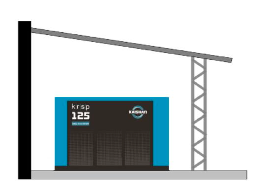
If you install your compressor outside, make sure it is protected from the elements, direct sunlight and temperature extremes.
Room Layout Considerations
Proper room layout is essential for safe and efficient operation. When planning your industrial air compressor system diagram, allocate sufficient space for maintenance access. Technicians need room to service components, replace parts, and perform routine maintenance without obstruction. Follow manufacturer recommendations for minimum clearances—typically 3 feet on sides and rear, and 3 to 5 feet in front of control panels.
Consider the flow of air and maintenance traffic in your layout. Arrange equipment to allow natural airflow patterns and logical maintenance sequences. Group related components together to minimize piping runs and pressure drops.
Proper clearance requirements extend beyond the compressor itself. Include space for air receivers, dryers, filters, and other system components. Ensure there's adequate overhead clearance for lifting equipment during major servicing. The room should also accommodate future equipment additions or system expansions.
Flooring is another critical consideration. The compressor room should have a level, reinforced concrete floor capable of supporting the equipment weight. Include floor drains for condensate disposal and consider vibration isolation measures to prevent equipment damage and noise transmission.
To allow adequate spacing for operation and maintenance, you should place your compressor at least three feet away from walls or other equipment. Refer to your machine’s installation manual for manufacturer’s recommendations.
You can place more than one compressor in the room, but you’ll want to make sure one compressor is not blowing exhaust air onto another.
You’ll want to locate your new compressor at least three feet away from walls and other equipment.
Compressor Room Ventilation Design
Why Ventilation Matters
Proper ventilation is critical for compressor performance and longevity. Compressors convert electrical energy into compressed air, but the process is only about 10-15% efficient—the remaining energy becomes heat. Without adequate ventilation, this heat accumulates, causing overheating that reduces efficiency, increases wear, and can lead to premature failure.
Heat dissipation requirements vary by compressor size and type, but as a general rule, maintain room temperatures between 40-100°F (4-38°C). For every 20°F temperature rise above 100°F, compressor efficiency decreases by about 2%, while maintenance requirements increase significantly.
Air quality considerations are equally important. Ventilation removes contaminants like dust, chemical fumes, and moisture that can damage equipment and degrade air quality. Poor ventilation leads to contaminated intake air, which accelerates wear and increases maintenance costs.
Proper compressor room ventilation calculation must account for both heat removal and air quality. Inadequate ventilation creates a vicious cycle: higher temperatures reduce efficiency, causing the compressor to run more, generating even more heat. This cycle dramatically increases energy consumption and operating costs while shortening equipment life.
Calculating Ventilation Needs
Calculating proper ventilation requirements involves determining the heat load and required airflow. The basic formula for compressor room ventilation calculation is:
CFM = (Total Heat Input in BTU/hr) / (1.08 × Temperature Difference)
Total heat input includes compressor heat (approximately 2,545 BTU/hr per horsepower), plus heat from other sources like dryers and pumps. For example, a 50 HP compressor generates about 127,250 BTU/hr. If you want to limit temperature rise to 20°F, the required airflow would be:
CFM = 127,250 / (1.08 × 20) = 5,892 CFM
Practical examples help illustrate this calculation. For a 25 HP system in a 1,000 sq ft room with 10 ft ceiling:
-
- Heat input: 25 HP × 2,545 BTU/hr = 63,625 BTU/hr
- Desired temperature rise: 15°F
- Required CFM: 63,625 / (1.08 × 15) = 3,923 CFM
This means you need ventilation capable of moving nearly 4,000 cubic feet of air per minute to maintain proper temperatures. A visual diagram of ventilation setup would show intake vents near floor level on one side of the room and exhaust vents near the ceiling on the opposite side, creating cross-ventilation that removes hot air effectively.
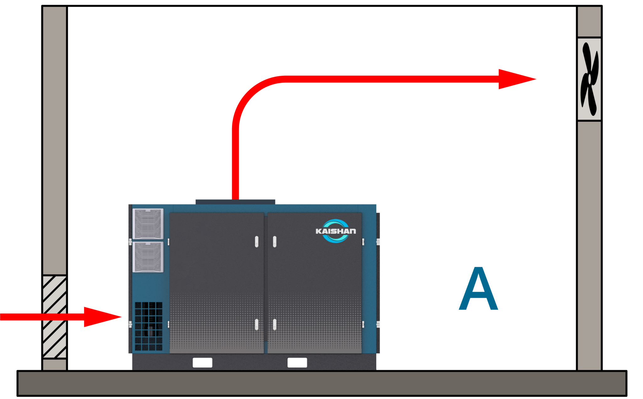
Depending on ambient conditions, you may only need louvered inlets and outlets to keep cool a smaller compressor.
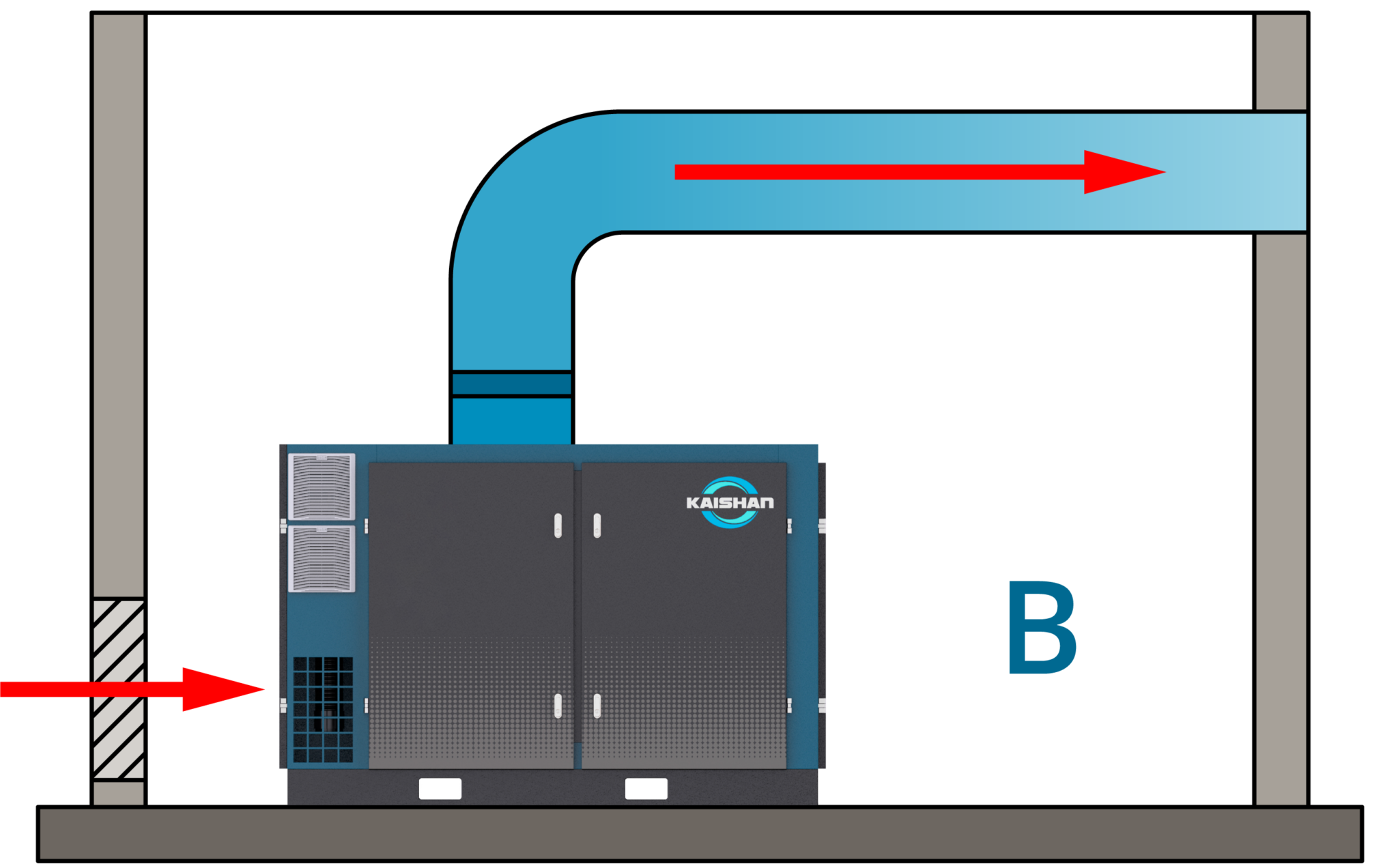
For larger units (25 HP and above), you probably will need a fan (not shown) and ductwork to remove heat.
Ventilation System Options
Several ventilation system options are available, each with advantages for different situations:
Forced Air Systems use fans to actively move air through the compressor room. These systems provide precise control over airflow and can handle large heat loads. Options include:
-
- Exhaust fans only (relying on passive intake)
- Supply and exhaust fans (balanced system)
- Powered louvers with thermostatic control
Forced air systems are ideal for larger installations or facilities with high heat loads. They provide consistent ventilation regardless of outside conditions but require ongoing energy input and maintenance.
Passive Ventilation approaches rely on natural convection and wind effects. These include:
-
- Gravity vents and louvers
- Ridge vents and roof ventilators
- Building orientation to take advantage of prevailing winds
Passive systems have lower operating costs and maintenance requirements but are less effective in large installations or areas with minimal natural airflow.
Here's a comparison table of ventilation options:
| SYSTEM TYPE | INITIAL COST | OPERATING COST | MAINTENANCE | EFFECTIVENESS | BEST FOR |
|---|---|---|---|---|---|
|
Forced Air (Exhaust Only) |
Low |
Medium |
Low |
Medium |
Small to medium rooms |
|
Forced Air (Balanced) |
Medium |
High |
Medium |
High |
Large installations |
|
Passive Ventilation |
Low |
Very Low |
Very Low |
Low to Medium |
Small rooms, moderate climates |
|
Hybrid (Passive + Boost Fan) |
Medium |
Low |
Low |
Medium-High |
Most installations |
For most industrial applications, a hybrid system offers the best balance of cost and effectiveness, using passive ventilation with thermostatically controlled boost fans for additional cooling when needed.
In northern climates, it’s possible to save significant amounts of energy by recovering the heat removed from the compressed air system in the winter. A damper directs the air toward an outside vent in the summer. In the winter, the air goes toward space heating or preheating other operations.
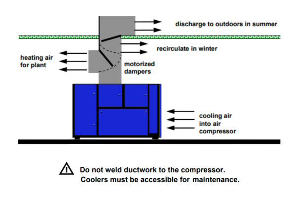
It’s also possible to recover most of the heat your compressor generates, especially in cooler, northern climates.
Air Compressor Ducting Design
Understanding Ducting Requirements
Proper air compressor ducting is essential for efficient compressed air delivery. Ducting requirements begin with proper sizing—undersized ducts create excessive pressure drops, while oversized ducts increase costs without benefits. The goal is to balance flow velocity with acceptable pressure loss.
For main distribution lines, maintain velocities between 20-30 feet per second (fps) to minimize pressure drops while preventing oil and moisture from settling out. For branch lines, velocities up to 40 fps are acceptable. Pressure drop should not exceed 3-5 PSI from the compressor to the farthest point of use.
Material selection is equally important. Options include:
-
- Black steel pipe (most common, durable but prone to corrosion)
- Copper pipe (corrosion-resistant but expensive)
- Aluminum pipe (lightweight, corrosion-resistant)
- PVC pipe (low cost but not suitable for high pressures or temperatures)
For air compressor ducting, black steel remains the industry standard for industrial applications due to its strength and pressure rating. However, aluminum systems are gaining popularity due to their corrosion resistance and ease of installation.
Designing Efficient Ductwork
Designing efficient ductwork requires attention to several key factors. Minimizing pressure drops is paramount—every PSI lost in distribution is wasted energy. Achieve this through:
-
- Using gradual bends (long-radius elbows) instead of sharp turns
- Keeping pipe runs as short and direct as possible
- Avoiding unnecessary fittings and restrictions
- Sizing pipes appropriately for the flow rate
Layout best practices include installing a loop system rather than dead-end branches. A loop system provides air from two directions, reducing pressure drops and balancing the system. Install drop legs from the top of main lines to prevent moisture carryover, and slope pipes toward drain points (minimum 1/8" per foot).
For compressed air system design, always include proper filtration and drying at strategic points. Install main filters at the compressor room and additional filters at points of use where air quality is critical. This staged approach ensures clean air throughout the system while minimizing pressure drops.
Installation Tips
Proper installation of ducting ensures long-term performance and reliability. Begin with sealing and insulation—all joints should be sealed with appropriate thread sealant (never Teflon tape on threaded connections, as it can shred and enter the system). Insulate pipes in unconditioned spaces to prevent condensation and maintain air temperature.
Condensate management is critical for system performance. Install automatic drain traps at all low points, including aftercoolers, receivers, filters, and dryers. These traps should discharge to proper drain lines or collection systems, not onto the floor.
Follow these step-by-step instructions for ducting installation:
1. Plan the entire system layout before beginning installation
2. Install main headers first, using proper supports every 6-8 feet
3. Slope pipes 1/8" per foot toward drain points
4. Install isolation valves at key points for maintenance access
5. Add pressure gauges at strategic locations for monitoring
6. Install branch lines with drop legs from the top of mains
7. Connect equipment using flexible connectors to reduce vibration transmission
8. Pressure test the system at 1.5 times operating pressure before use
9. Check all connections for leaks using soap solution or ultrasonic detector
10. Label all pipes and valves for easy identification
Electrical Requirements for Industrial Compressors
Power Supply Considerations
Industrial compressors have significant electrical requirements that must be carefully addressed during installation. Voltage requirements vary by compressor size—smaller units (under 10 HP) typically use 230V single-phase power, while larger industrial compressors require 460V three-phase power.
Circuit protection is essential for safety and equipment protection. Install properly sized circuit breakers or fuses as specified by the manufacturer. Overcurrent protection should be sized at 125-150% of the compressor's full load current to allow for startup surges while providing adequate protection.
When designing a compressor, consider the electrical service capacity of your facility. Ensure your service entrance and distribution panels can handle the additional load without exceeding 80% capacity. For large compressors (25 HP and above), you may need a dedicated service or separate electrical service.
Motor starting methods also impact electrical requirements. Across-the-line starting is simple but creates high inrush current. Reduced-voltage starters or variable frequency drives (VFDs) reduce starting current and provide better control, though at higher initial cost.
Wiring Best Practices
Proper wiring ensures safe, reliable operation of your compressor system. Conduit selection depends on the installation environment—use rigid metal conduit (RMC) or intermediate metal conduit (IMC) for exposed locations in industrial settings. For less demanding environments, electrical metallic tubing (EMT) may be sufficient.
Grounding requirements are critical for safety. All compressor equipment must be properly grounded according to NEC (National Electrical Code) requirements. This includes the compressor frame, motor, control panel, and any other metallic components. Use grounding conductors sized appropriately for the circuit ampacity.
Safety tips for electrical installation include:
-
- Always de-energize circuits before working on them
- Use lockout/tagout procedures during maintenance
- Install emergency stop buttons at compressor and remote locations
- Provide proper clearance around electrical panels (36 inches minimum)
- Use properly sized wire for the run length and load
- Install surge protection for sensitive electronic controls
- Label all circuits clearly for easy identification
Follow manufacturer specifications precisely when connecting control wiring. Improper wiring can damage expensive control components and create safety hazards. When in doubt, consult a qualified electrician experienced with industrial compressor installations.
Step-by-Step Installation Process
Equipment Unpacking and Inspection
Begin the installation process with careful equipment unpacking and inspection. Create a pre-installation checklist that includes verifying all components have arrived, checking for shipping damage, and confirming the equipment matches your order specifications.
During unpacking, use appropriate lifting equipment and follow rigging guidelines to prevent damage. Remove all packing materials and protective coverings, but retain documentation, manuals, and warranty information for future reference.
Damage assessment should be thorough. Check for visible dents, scratches, or misalignment. Inspect electrical components for loose connections or damage. Verify that rotating parts move freely and that control panels are intact. Document any damage with photographs and contact the supplier immediately if issues are found.
Before proceeding with installation, ensure you have all necessary tools, materials, and personnel available. Review the installation manual thoroughly and clarify any questions with the manufacturer or technical support.
Mounting the Compressor
Proper mounting is essential for compressor performance and longevity. Begin by preparing the foundation—a level, reinforced concrete slab capable of supporting the equipment weight with adequate safety margins. The foundation should be isolated from building structures to prevent vibration transmission.
Vibration isolation is critical for reducing noise and preventing equipment damage. Install vibration isolation pads or springs between the compressor and foundation. These should be selected based on the compressor weight and operating speed to provide effective isolation at the dominant frequencies.
Anchoring requirements vary by compressor size and type. Smaller units may only require bolting to the foundation through isolation pads, while larger compressors need substantial anchor bolts embedded in the concrete. Follow manufacturer specifications for anchor type, size, and torque requirements.
When positioning the compressor, ensure proper clearances for maintenance access and airflow. Level the unit using shims if necessary, and verify alignment with connected equipment. Once positioned, tighten anchor bolts to the specified torque in a cross pattern to ensure even pressure distribution.
Connecting Piping and Ducting
Connecting piping and ducting requires attention to detail to ensure leak-free operation. Begin with proper connection techniques—for threaded pipe, apply appropriate sealant to male threads only, avoiding the first two threads to prevent contamination. For flanged connections, use new gaskets and tighten bolts in a cross pattern to ensure even pressure distribution.
Leak testing procedures should follow installation. Pressurize the system to 1.5 times the operating pressure and check all connections with a soap solution or ultrasonic leak [detector. Repair any leaks before proceeding. Pay special attention to threaded connections, valves, and fittings, as these are common leak points.
When installing flexible connectors, ensure they're not over-compressed or over-extended. These connectors should be installed without stress to prevent premature failure. Support piping properly to prevent weight from hanging on the compressor or equipment.
Install pressure gauges and flow meters at strategic locations for system monitoring. Label all pipes and valves clearly for easy identification during operation and maintenance.
Electrical Connections
Electrical connections require strict adherence to safety procedures. Begin with safety precautions—de-energize all circuits, use lockout/tagout procedures, and verify zero voltage before working on any electrical components. Use properly rated tools and personal protective equipment.
Proper wiring methods include using correctly sized conductors for the load and run length. Follow NEC requirements for conduit fill, wire bending radius, and support. Install appropriate disconnect switches and overload protection as specified by the manufacturer.
Grounding is critical for safety—connect all equipment grounds to the building grounding system using properly sized conductors. Verify continuity and low resistance in all ground connections. Install surge protection for sensitive electronic controls.
Make control connections according to the wiring diagram, ensuring proper polarity and secure connections. Label all wires clearly for future troubleshooting. Once all connections are complete, perform a thorough visual inspection before applying power.
Initial Startup and Testing
Initial startup should follow a systematic approach to ensure proper operation. Begin with commissioning procedures outlined in the manufacturer's manual. This typically includes checking oil levels, verifying rotation direction, and setting control parameters.
Before starting the compressor, ensure all valves are in the correct position, guards are in place, and personnel are clear of the equipment. Start the compressor unloaded and allow it to run for a few minutes to build oil pressure and stabilize temperature.
Performance verification involves checking operating pressures, temperatures, and currents against manufacturer specifications. Monitor for unusual noises or vibrations. Test all safety controls and shutdown features to ensure proper operation.
Gradually load the compressor and monitor system performance. Check for leaks, verify pressure regulation, and ensure the unit cycles properly under varying loads. Document all operating parameters for future reference and baseline comparison.
Post-Installation Testing and Optimization
System Testing Procedures
After installation, thorough testing ensures your system operates as designed. Pressure testing should be conducted at 1.5 times the maximum operating pressure for a specified duration (typically 30 minutes). Monitor pressure gauges for any drops, which indicate leaks in the system.
Leak detection is critical for system efficiency. Use an ultrasonic leak detector to identify even small leaks that might not be audible. Common leak points include threaded connections, valves, hoses, and quick-connect fittings. Repair all leaks before proceeding—studies show that compressed air systems typically lose 20-30% of their air to leaks.
For how to setup air compressor properly, create a testing checklist that includes:
-
- Verifying all safety devices function correctly
- Testing automatic drain traps
- Checking control system operation
- Verifying pressure settings and regulation
- Monitoring power consumption under various loads
- Measuring air quality at points of use
- Documenting baseline performance metrics
Conduct these tests under various operating conditions to ensure the system performs reliably across its expected range of operation.
Performance Optimization
Once testing is complete, focus on optimizing system performance. Efficiency adjustments include setting the appropriate pressure band—the difference between load and unload pressures. A narrower band (10 PSI or less) improves efficiency but may cause more frequent cycling. Find the balance that works for your application.
Control system programming is crucial for modern compressors. Set up proper sequencing for multiple compressors to ensure they operate in the most efficient combination. For variable speed compressors, program the control curves to match your specific demand patterns.
Consider implementing advanced control strategies like network controls that coordinate multiple compressors or demand-side controls that optimize air usage. These systems can significantly improve efficiency, especially in facilities with varying demand patterns.
Monitor key performance indicators (KPIs) like specific power (kW/100 CFM) to measure efficiency improvements. Establish baseline measurements and track changes as you implement optimization measures.
Maintenance Considerations for Your Installation
Regular Maintenance Requirements
Establishing a regular maintenance schedule is essential for preserving your installation investment. Scheduled service intervals should be based on manufacturer recommendations but adjusted for your specific operating conditions. Typical intervals include:
-
- Daily: Check oil levels, drain tanks, inspect for leaks
- Weekly: Check filters, test safety valves, inspect belts
- Monthly: Check oil quality, clean coolers, test controls
- Quarterly: Replace filters, inspect valves, check alignment
- Annually: Replace oil, inspect motor bearings, test safety systems
Key maintenance points include air filters (replace when differential pressure reaches 10 PSI), oil filters (replace at recommended intervals), and separators (replace every 4,000-8,000 hours depending on type). Keep detailed maintenance records to track performance and identify trends.
Consider implementing a predictive maintenance program using vibration analysis, oil analysis, and thermography to identify potential issues before they cause failures. This approach can significantly reduce unplanned downtime and repair costs.
Monitoring System Performance
Ongoing monitoring helps maintain optimal performance and identify developing issues. Key metrics to track include:
-
- Pressure at compressor discharge and various points of use
- Temperature at multiple locations in the system
- Power consumption (kW) and specific power (kW/100 CFM)
- Flow rates and demand patterns
- Air quality (dew point, oil content, particulate levels)
Early warning signs of problems include increasing pressure drops across filters, rising temperatures, decreasing flow rates, and increasing power consumption for the same output. Unusual noises or vibrations also indicate potential issues that need attention.
Install permanent monitoring equipment where possible, with data logging capabilities to track trends over time. Set up alarms for critical parameters that fall outside normal ranges. Regular review of this data helps optimize performance and plan maintenance activities effectively.
Frequently Asked Questions
Conclusion
Proper industrial air compressor installation is a complex process that requires careful planning, precise execution, and ongoing attention to detail. From initial design considerations to final testing and optimization, each step plays a crucial role in creating a system that delivers reliable, efficient compressed air for your operations.
By following the guidelines in this comprehensive guide, you'll ensure your installation meets all technical requirements, safety standards, and performance expectations. Remember that the investment in proper installation pays dividends through reduced energy costs, extended equipment life, improved air quality, and minimized downtime.
Whether you're installing a small system for a workshop or a large industrial installation, the principles remain the same: thorough planning, quality components, skilled installation, and diligent maintenance. By adhering to these principles, you'll create a compressed air system that serves your needs reliably for years to come.
Ready to optimize your compressed air system? Download our free Industrial Air Compressor Installation Checklist to ensure you don't miss any critical steps. For personalized assistance with your installation project, contact our team of compressed air experts today!
